The Sun with its immense energy stores and close proximity to Earth is a great celestial object to monitor at all wavelengths. What’s more, one can monitor activity on the Sun via indirect means. More precisely, it is possible to detect solar activity by monitoring the Earths magnetic field. It’s also possible to detect solar activity such as solar flares by monitoring Very Low Frequency (VLF) signal paths which use the Ionosphere as a means of propagation. Check out my SID receiver page.

I wanted to build a device which I could use to monitor geomagnetic storms from my location. I initially built a simple magnetometer consisting of some magnets suspended by a thread (details found here). After a short time though, I noticed that I needed something better if I was to do extensive recordings. I did some searching online and came across a compass magnetometer design that caught my attention.
The schematic depicted below is from AuroraWatch and is the one I decided to build. All of the parts I acquired from Radio Shack or Wal-Mart. The electromagnet is a reed relay coil from Radio Shack (275-233). The op-amp is a 741 wired as a current-to-voltage amplifier. The three 150ohm resistors are wired in parallel because the IR LED is very current hungry, and wiring the resistors in parallel increases their total power dissipation. In other words if you only use one 150ohm resistor you will smoke it! I had to add more capacitance on the positive side of the dual polarity power supply to help with the high current usage of this LED.

I have included a picture of the completed magnetometer and the power supply. I used a kit box to enclose the components and keep ambient light out of the light gate. As stated, I used a 200 ohm reed relay coil for the electromagnet. I have placed a North arrow in the image to allow for a better idea of where the components should go.

The following image is the finished dual polarity power supply that is required to power the Op741. The IR LED is very current hungry so I had to use a 1.2 amp transformer to provide adequate power to the circuit.

The recording device is a DI-194RS. This A/D is capable of connecting to a computer with the use of a serial cable. This is ideal for prolonged unattended recordings, and a feature which I used to it’s fullest.
The compass magnetometer is surprisingly sensitive, capable of detecting a human body at a distance of around three meters. Thunderstorms tend to cause the magnetometer to behave very erratically. Furthermore, during geomagnetic storms the meter readings are all over the place. The following two images show an example of a solar event being detected by a magnetometer. The first image is from the Fluxgate Magnetometer in Gakona Alaska for August 30, 2006. The second image is from my homemade compass magnetometer for roughly the same time period. As can be seen from the images, the small solar event which took place at around 5:00 a.m. local time was recorded by both magnetometers.


Fluxgate Magnetometer
As well as the compass magnetometer has worked for me I haven’t been completely satisfied with it’s performance. After all it is a very simple and error prone magnetometer. What I really wanted was a fluxgate magnetometer. Thankfully technology has come a long way and it’s now possible to build a fluxgate magnetometer with relative ease. I came across this sensor from FGM Magnetic Field Sensors called the FGM-3. The FGM-3 is sensitive enough to detect the Earth’s geomagnetic field and it’s variations so don’t be fooled by it’s small size and affordable price tag. These sensors really work! The only drawback to the FGM family is that they are sensitive to temperature variations as most fluxgate sensors in this price range are. Not to worry there are things you can do to help with this.
For geomagnetic monitoring additional voltage regulation of the FGM-3 power supply is needed. This can be easily accomplished by using two stages of voltage regulation. In my case I’m using a 12V regulator (7812) at the electronics side, and then a 5V regulator (7805) at the FGM-3 sensor side. This is in addition to the regulation in the main power supply. Tantalum capacitors are used on the outputs of each of the regulators for maximum effectiveness.
For controlling temperature induced errors as well as local magnetic disturbances on the FGM-3 I buried the sensor four feet under the Florida sand about one-hundred feet behind the house. The sensor was aligned in the East-West orientation (Y axis). I used a shielded cable for connecting the sensor to the electronics in the house. The FGM-3 was inserted inside a water sealed PVC pipe before burring. The second cable seen in the image below is for powering the calibration coil which I made for the FGM-3. The cylindrical coil was made to be twice as long as the FGM-3 and just a bit larger in diameter to allow the insertion of the sensor. In this manner, I’m able to test/calibrate the sensor despite it being four feet below ground. A small battery (few volts), variable resistor and ampmeter is all that’s needed to calibrate the FGM-3. As an example of the low currents needed I normally calibrate the sensor with 50uA of current which with the coil in use generates about ~35nT through the axis of the sensor. When not in use the calibration coil feed leads are not connected and are left open. The reason is that the calibration coil can act as a shorted turn to the oscillator coil inside the FGM-3 reducing sensitivity or even shutting down the FGM-3 (so long as the calibration coil is kept shorted). The calibration coil is an extra step and adds a bit more work, but it’s well worth the effort in the end.

I have to admit that I wasn’t sure what to expect after setting this magnetometer up for the first time. I figured that I’d be able to detect strong solar storms with it, but that most of the weak activity would be missed. Well, I was pleasantly surprised. Below is a typical 48 hour plot during a quiet geomagnetic period (zoomed in). I have labeled the times of the day where interesting activity has occurred. The sinusoidal pattern seen during the daylight hours is called the solar quiet day variation Sq, and is a natural geomagnetic field diurnal perturbation which is generated by the ionospheric dynamo. Therefore, these perturbations do not originate from within the Earth, but from above via currents flowing within the ionosphere thanks to the ionizing energy from the Sun.

These perturbations are small, in the order of say 50nT peak-to-peak or less. In the above plot my magnetometer was set to the most sensitive setting. On this setting and using the calibration coil at 50uA generating 35nT the output of the meter is about 3/4 full scale. Therefore, one can estimate that on the first day in the above plot the peaks where at about 20nT from center. These are small variations indeed! As mentioned earlier, the sensor is in the East-West orientation. To confirm that the above variations are indeed natural one can compare these plots with some professional fluxgate magnetometers. I like to use the USGS real time magnetometer chain for this purpose. Be sure to set the component monitored to “E”. In these plots one can follow the passage of the Sun as it crosses the American continent just by interpreting the rise and fall of each magnetometer in the chain. One other thing to note is that although this diurnal perturbation occurs every day it doesn’t always occur at the same levels. A perfect example is the second day on the above plot. For whatever reason the morning pattern was much attenuated as well as was the afternoon one. Below is another example of the Sq pattern. The two pulses to the far left are 35nT calibration signals (from the calibration coil) to give an idea of the strength of these daily variations. The red lines are just for reference.

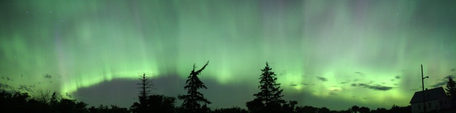
There’s no doubt that this magnetometer is capable of detecting even small geomagnetic storms. Below is an example of a somewhat active day. On July 22, 2009 Earth was impacted by a solar wind stream which at times reached Kp 6 levels. On the previous day the graph only showed the normal Sq pattern (like above). At around 0245UTC the storm commencement was detected and the ensuing oscillations where also recorded. Things began to quite back down after about 0930UTC. Up in the United Kingdom at around 0600UTC, Paul Nicholson’s VLF receiver began to pick up risers (VLF emissions) and aurora chorus activity. Also, high latitude observers where treated to aurora activity. I add this simply to show how global in scope these events are.

Thanks for reading, and have fun!
Fat Quarters no longer has kits. Their electronics store is closed. Might want to update this website.
I would love to discuss this experiment in greater details if you have time? My email is. We are working on a project which uses magnetometers and would like some assistance and feedback.