
8Radio astronomy is a relatively young field. At least when compared to optical astronomy anyway. Some of the early names in this field are Karl Jansky, and Grote Reber. These men made their great discoveries during the 30’s and 40’s. Grote Reber for example discovered that contrary to the theory of thermal radiation, radio signals coming from outer space were weaker at higher frequencies. The theory that explains this is synchrotron radiation. This is good news for the amateur astronomer as lower frequency radio equipment is usually easier to work with than higher frequency radio equipment. Synchrotron radiation is particularly strong in the frequency range between 38MHz and 700MHz. There are a number of recognized radio astronomy quiet frequency in this range as well so this is also good news.

I have always been interested with anything radio. So naturally, trying my hand at radio astronomy is something I’ve wanted to attempt for some time now. I have to admit that this project was full of difficulties and disappointments. Nevertheless, after months of on and off attempts at trying to get my radio telescope working I think I finally have a working unit.
When it comes to a radio telescope the components used are a directional antenna or dish antenna, a sensitive receiver, and a recording device. Dish antennas are normally used more because they remain effective over large frequency ranges. This is important when one is trying to monitor many frequencies instead of just one. With this said, I came across a great website which sells some of the components needed to build a radio astronomy telescope. The website is MTM Scientific, and I purchased the CATV tuner and 10 element Yagi from this website. The CATV tuner is used to tune into 611MHz which is a recognized radio astronomy quiet frequency. The 10 element Yagi is tuned for this 611MHz frequency as well. I’m using a DI-194RS analog-to-digital converter attached to a PC for the recording device.
I have had a lot of trouble getting the CATV tuner to produce a signal on its IF output pin. The IF pin is used as the signal output from the CATV tuner which is then AM demodulated using a 1N34A germanium diode and DC amplified using a INA122 instrumentation amplifier. The amplified DC signal is then fed into a recorder. This is the standard configuration for a basic radio telescope. For whatever reason though, I can not get a strong enough signal from the IF pin when tuned to a TV station on channel 38 which is just above 611MHz (Ch 37). On the other hand I can get a perfect IF signal from the CATV tuner when tuned to a lower frequency like say a station on the FM radio band. I really have no clue at this time why this is so, but it has been the source of all my problems so far. It’s almost like the two upper bands of the CATV tuner are failing to generate a usable IF signal. If anyone has any idea why this is so, or has some advice for trouble shooting this problem please email me.
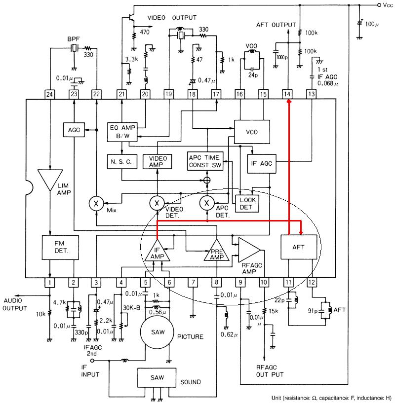
I’m not one to give up even after months of failures so I continued to look for solutions to this problem. What I finally discovered is that for this particular CATV tuner, the Panasonic ENG26104G, it is also possible to monitor the AFT pin for variations in signal strength. The AFT (Automatic Fine Tuning) circuitry for analog video signals provides feedback to analog tuning circuitry to lock in or tune in a channel according tosignal strength. The key word in the definition of AFT is “signal strength”. In other words, the demodulated DC voltage at the AFT pin is proportional to the strength of the signal in the IF stage. This makes sense as the AFT voltage is used to vary the internal oscillator frequency to keep the tuner on frequency. To see a schematic of the LA7577 IF chip used in this CATV tuner click here. I have been using the AFT pin of the CATV tuner to monitor signal strength variations on the 611MHz quite frequency for some time now with promising results.
My goal for this project was to detect Cassiopeia A. Cassiopeia A is the strongest radio source aside from the Sun in the sky and is about 11,000 light years from Earth. What’s funny about this supernova remnant is that it is very hard to see visually. Only very long exposures can make this nebula out yet it is incredibly bright in the radio spectrum! Here is one of my first successful recordings of Cassiopeia A. It was taken on November the 15th, 2008. The hump in the middle of the plot with the marker is Cassiopeia A. For these recordings the antenna is positioned at different points on the meridian depending on what object is being observed. The telescope then drift scans that region of the sky.

Here’s a two day plot of Cassiopeia A with the second day superimposed over the first. The marker is marking the transit of Cassiopeia A for the first day, 20:04 local time 11/16/08. On the second day Cassiopeia A transited about four minutes earlier. For this recording I placed a 1200uF capacitor across the output of the CATV tuner to smooth out the plot some.

This radio astronomy project has been a real challenge for me to get working correctly. All my troubles have centered around the IF output of the CATV tuner. I have so far not been able to get the IF pin to work correctly even after trying two different tuners. Therefore, I don’t know if I have had the bad luck of getting two defective tuners or if there is more to the IF issue.

What matters is that the tuner is working ok using the AFT pin so not all is lost. I would like to try detecting some more object in the future. I would like to try my hand at Sagittarius A and Cygnus A. These two objects are the other heavy hitters in the radio spectrum and I think my receiver might be sensitive enough to detect them. It might also be possible to detect pulsars although I’m not holding my breath on this one.
The image to the right is of the CATV tuner receiver with the three voltage (5V, 12V, 30V) board under testing. I plan on enclosing the receiver in a steel cage for shielding because it tends to detect body movements near its vicinity. After all, these tuners are always shielded when inside TVs and VCRs…
I hope the information in this page might be helpful to others having the same type of trouble as I am with this CATV tuner. Or maybe it might inspire someone to give this project a try. Bottom line, this project has been a great learning experience for me, so although I had all kinds of problems I’m glad I kept at it!
Good luck!